Pipes shell in process piping and pipelines systems are generally under several loading conditions; mainly resulting from internal and external pressure, dead loads such as pipe and its content weight, occasional loads such as wind, snow, earthquake or thermal expansion loads. These loads generate primary or secondary general membrane stresses in the pipe shell and should be analyzed according to the relevant design codes and specifications.
Regarding to table 17 of Roark’s formula hand book [7], the total shear load Q which is carried by the pipe shell is defined by a tangential shear force sinusoidal function as follows (figure 1):
1-Introduction
Local Stresses in Large Pipes at Support Locations
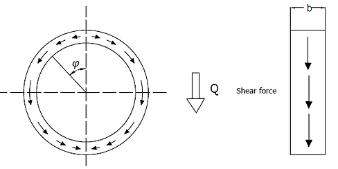
Figure 1: shear force sinusoidal
(1)
Shells of large bore pipes are more vulnerable to deformation than smaller ones because generally they have a higher r/t ratio. Once a pipe shell deforms locally, a circumferential bending moment and a direct tangential force will be generated in the pipe shell. Theses local loads which exist in a complex pattern are basis of local stresses in a discontinuity area. According to the Saint-Venant principle, for this complex pattern, a fuzzy zone could be defined in each side of the support with one diameter wide, see figure 2.


Figure 2: Local circumferential stresses in discontinuity area (affected zone)
The local stresses must be considered in stress combination including the general membrane stresses at the discontinuity area. For evaluation the local stresses, there are some semi-empirical approaches such as Roark’s and Zick’s methods which are discussed as follows. [1]
2- Roark’s Method for Saddle Supporting
Roark considered saddle supports for large pipes. On the saddle support, pipe shell deforms under its own weight, figure 2. As mentioned early, this deformation causes a circumferential bending moment and direct tangential force in the shell. According to the Roark’s investigation, the maximum circumferential moment and direct tangential force occurs at 15 deg above the saddle tips. Those stresses are independent of saddle width, however decreases as the saddle angle increases.
The maximum value of those localized stresses could be determined by following empirical equation:
(2)
(3)
(4)
The equation (3) is applicable for very thin-wall pipes and adopted by American Water Works Association (AWWA). Equation (4) is suitable for thicker-wall pipes and used by Ductile Iron Pipe research Association (DIPRA).
Main part of the stress given by equation (2) is circumferential bending stress which includes shear stress and local tangential membrane stress resulting from support load. [1]
3- Zick Method for Saddle Supporting
For evaluation of local stresses resulting from saddle support in large pipes, Zick has developed a semi-empirical procedure which is recommended in ASME BPVC section VIII, Div I and also is a basis for saddle support design in British Standard, BS-5500.
As mentioned in the introduction, far away from the support location, the total shear load Q is carried by pipe shell with a tangential shear force sinusoidal function, but in the fuzzy zone, the local stresses are generated in a complex pattern. [8]
In order to determine these local stresses, Zick considers a stiffening ring over the saddle and assumes that the shell maintained in a roundness shape, therefore the shear forces distribution could be considered the same as undisturbed portion of pipe section. With a fixed ring at the horn of saddle, when the shear force transfers from pipe to saddle, it generates circumferential bending moments in the pipe shell as figure 3.

Figure 3: circumferential bending moment and tangential shear force sinusoidal function in a pipe saddle
This circumferential bending moment could be determined as [8]:
(5)
The maximum moment occurs at the horns of saddle.
The direct tangential force, P, which generates circumferential local membrane stresses at horns of saddle, is calculated as follows [8]:
(6)
Where is the circumferential bending moment at the top of the ring. For finding which is function of saddle refer to section 6.7.3 of [1]. The circumferential bending stress at the ring could be calculated by dividing the circumferential bending moment by section modulus of the ring and the tangential stress is determined by dividing the tangential force P by cross-section area of the shell-ring combination.
When there is no stiffening ring on the shell, the shear forces tend to concentrate near horn of the saddle. In this case, according to the zick’s observation, may be considered smaller than the value calculated in equation (6); therefore a value of Q/4 is used as a reasonable direct tangential force.
By replacing the pipe radius instead of ring radius in equation (5), the local circumferential bending and membrane stresses could be derived as follows: [1]
(7)
(8)
4- Supporting the bare shell
In the Zick’s approach, a circular ring model for saddle supports is used for evaluation the localized stresses. The circumferential moments and tangential forces are assumed to be generated because of shear forces; so if the saddle angle is considered zero, the maximum bending moment occurs at the support point and could be calculated as 0.239Qr, see figure 6. [1]

Figure6: circumferential bending moment and tangential shear force in a bare shell pipe
Zick’s assumes the effective ring width is four times of shell radius which is equal to fuzzy zone width; so the maximum stress at shell could be determined as:

(16)
Since equation (1) is independent of pipe diameter, it is unfavorable for application; on the other hand, there is a (r/t) factor in Roark’s formula which makes this approach more suitable; however this formula is for saddle angle more than 90 deg and there is no case of zero angle which implies a bare pipe.
In dealing with the above situation, one solution mentioned in [1] is to find a relation between the artificial moments determined by Zick’s model and compare it with Roark’s formula.
Referring to table 6.5 of [1] in which is tabulated versus saddle angles, the value of is reduced as saddle angle decreases. So the value of for a bare supported pipe may be assumed as its value at 70 deg. So:
(17)
Then
(18)
By substituting K in Roark’s formula:
(19)
Moreover, there is a direct tangential force which causes a circumferential local membrane compressive stress on the shell. This stress is determined by dividing the tangential force, P=0.239Q, by the effective cross-sectional area; therefore:
(20)
Where b is the width of stiffening ring and if there is no stiffening ring in the saddle support, it could be considered as the fuzzy zone width equal to 4r.

Where b is the width of stiffening ring and if there is no stiffening ring in the saddle support, it could be considered as the fuzzy zone width which is equal to 4r.
In large pipe supporting, the first question is whether the pipe could be supported on its bare shell or not? In order to answer this question, localized stresses in the bare shell support should be calculated and compared with allowable stresses.
For determination of the mentioned localized stresses, one of the most common methods is Roark’s ring model. This model considers the cross section of the pipe which rests on a support as a ring. It is assumed pipe weight and its content are transferred to the support by tangential shear stresses, as a sinusoidal function given in case 20, table 17 of [7]. These shear stresses generate bending moments, acts through the wall of the pipe in circumferential direction. The resulted stresses due to the bending moments depend on weight, radius and thickness of pipe.
The second method which has been developed in reference [1] is a combination of Zick and Roark’s methods for saddle supporting. In this method, a bare shell is considered as a zero degree saddle and the generated circumferential bending and tangential force are determined. The resulted stresses are also function of weight, radius and thickness of pipe
4-1- Roark’s Method for bare shell Supporting
In Roark’s method, it is assumed that the cross section of pipe is a ring and the total pipe weight and its content are transferred to the support by tangential shear stresses. This closed circular ring is a statically indeterminate beam and could be analyzed by Castigliano’s second theorem. According to case 20 in table 17 of [7], shear stresses are derived as equation (1) and its circumferential bending moment, for a thin wall pipe, is calculated as follows, see figure 4:

Figure 4: Loads in a Roark’s ring model
(9)
Where,
For determination of circumferential stresses, the circumferential bending moment should be divided by pipe section modulus in which an effective width of pipe, as shown in figure 5, is used.
(10)
Where,
(11)


Figure 5: Effective length of cross section resisting the bending moment
4-1-1-Effective length, , calculation
Calculation of the effective length which should be used in equation (11) has always been a controversial issue. One approach considers shear acts at a 45 degree angle, as figure 5; therefore, the value of b would be smaller value of 2r and This value is reasonable in structural design, however for piping design in combination with internal pressure, weight and thermal loads, the local stresses may lead to a significantly high value which is considered too conservative.
In the second approach which is based on Bendar’s observations, the actual effective length is considered as minimum of 4r and L/2, where L is support span. For ring girder supports, Troitsky considers the following value of for using in equation (11).
(12)
Where is the width of ring girder; therefore the effective ring could be determined as [12]:
(13)
By substituting equation (12) in (11) we have [12]:
(14)
may be calculated as follows:
(15)
In which is pipe mill tolerance,CA is corrosion allowance and is pad thickness.
4-2- Zick and Roark’s combined method for bare shell supporting
Q

